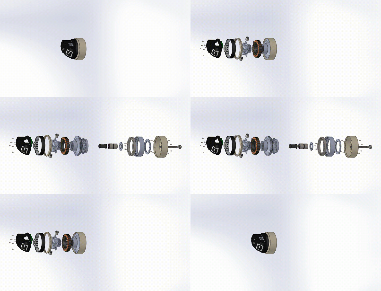
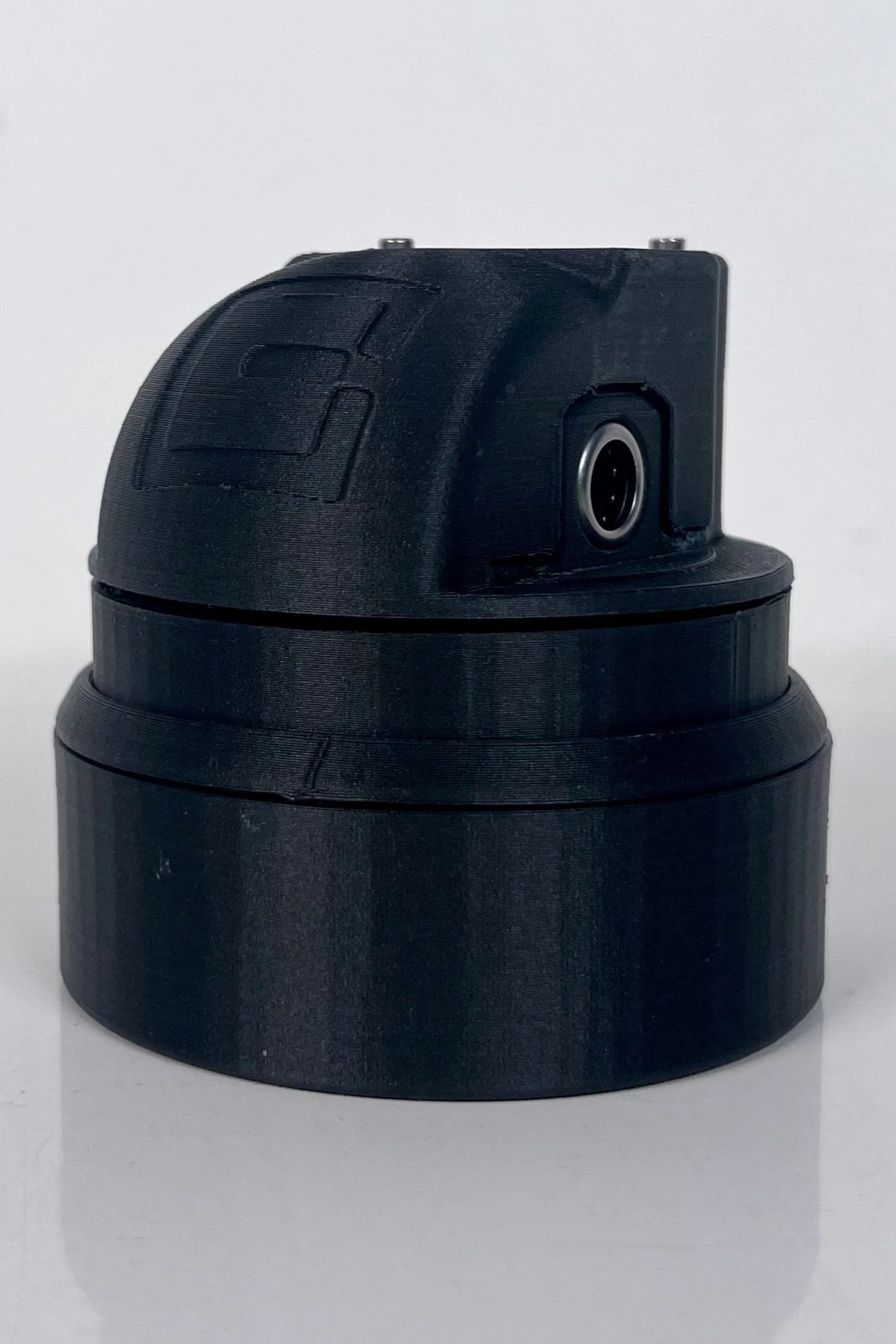
BiomechATRONIC Actuator
Integrated Brushless Outrunner Motor & Roller Screw Transmission
SolidWorks (Parts, Assemblies)
Finite Element Analysis (FEA)
Technical Drawings (CNC)
Generative Design (Fusion360)
Rapid Prototyping (FDM)
MIT Media Lab
Biomechatronics Group
Summer 2023
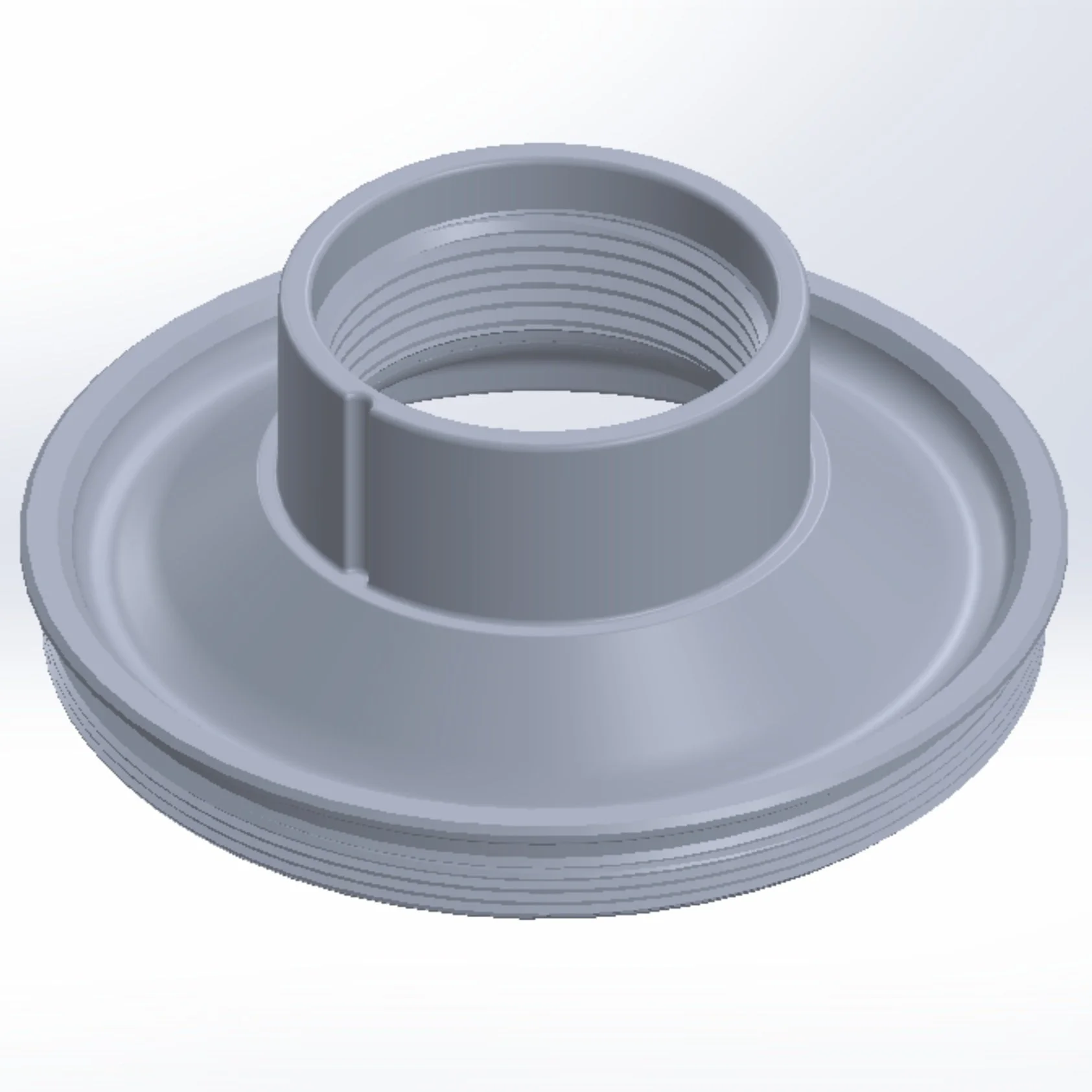
Parts & Subassemblies
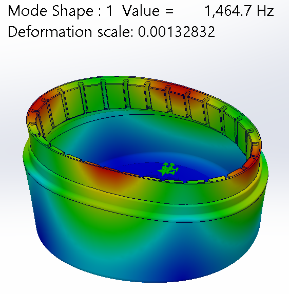
Finite Element Analysis
Each component was individually verified to meet stress (< 200MPa) and deflection (<.05mm) criteria.
Rotor Standoff Resonance
Rotor Total Deflection
Stator Total Deflection
Rotor Total Stress
Stator Total Stress
Technical drawings
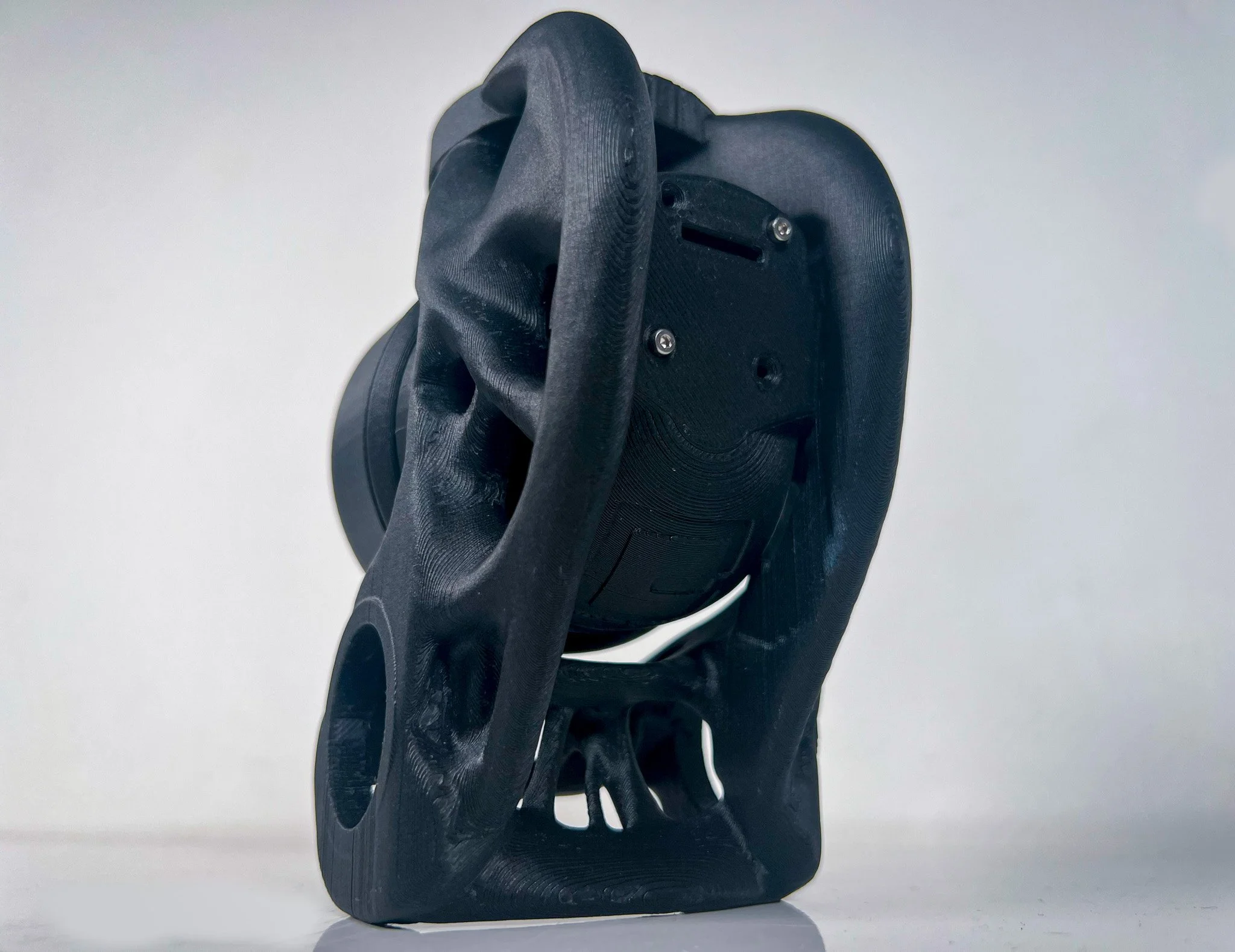
Generative Design
Ankle U-Bracket Frame,
Collaborated with Timber Carey
Stator Roller Frame, Generative Prototype
Stator Main Frame, Generative Prototype
U-Bracket Generative Model,
Loads and Moments
Rapid Prototyping (FDM)
Ideation, Iteration, Evolution [v1, v3, v8]
Generatively Designed U-Bracket
Project Details
-
Features a 300% increase in max torque output over the previous motor (1200Nm -> 4300Nm), with only a 20% increase in mass (450g -> 540g).
-
The motor is primarily constructed from Aluminum 7075-T6 for its light weight and high fatigue stress. In some cases, namely the rotor standoff, AZ91 magnesium alloy was preferred for a higher resonance frequency for a lighter weight.
-
Ph.D. Student Daniel Levine and Researcher Luke Hyman mentored me throughout the summer and taught me all the necessary design considerations. My designs for the actuator across eight iterations were independently developed. My designs were reviewed, critiqued, and approved by Dr. Chris Williams and Dr. Hugh Herr.
-
The Actuator and U-Bracket are currently being manufactured, and testing on the physical platform will begin in Fall 2023.

