2.007 Design and Manufacturing I
SCORPION - Sophomore Capstone
2.007 Design and Manufacturing I
SCORPION - Sophomore Capstone
Scorpion: Overview
Starting out simple
Before designing a robot to approach the main task, I built a testing platform to familiarize myself with the scale of the board, the machine shop, and the available components.
Kit Components
iDeation and refinement
Five concepts to transport plastic balls, followed by a decision matrix to evaluate the options and select the best.
Translated cardboard prototype to a manufacturable design from bolted sheet metal and aluminum L-brackets.
1. Approximation of the coefficient of static friction of rubber wheels on the MiniMe.
3. Calculation of the x-coordinate of the current CM using three scales to measure the normal force on each wheel.
5. Since the (x,y) position of the CM was outside of the purple region, I moved the battery, the heaviest component, lower. This reduced the y-position of the CM and the effect of theta on its displacement.
To prototype, I placed the battery behind the claw and made a hot glue and cardboard hinge to improve ground clearance.
I then designed a metal model with steel hinges, lowering the CM and moving the claw to avoid colliding with the ramp.
Vat of acid Challenge
After choosing the Static Claw, I developed five unique designs and another decision matrix to choose a final idea.
Simple CAD to reference while machining brackets and bending sheet metal.
A cardboard mock-up was created to test the claw and refine the finger angle.
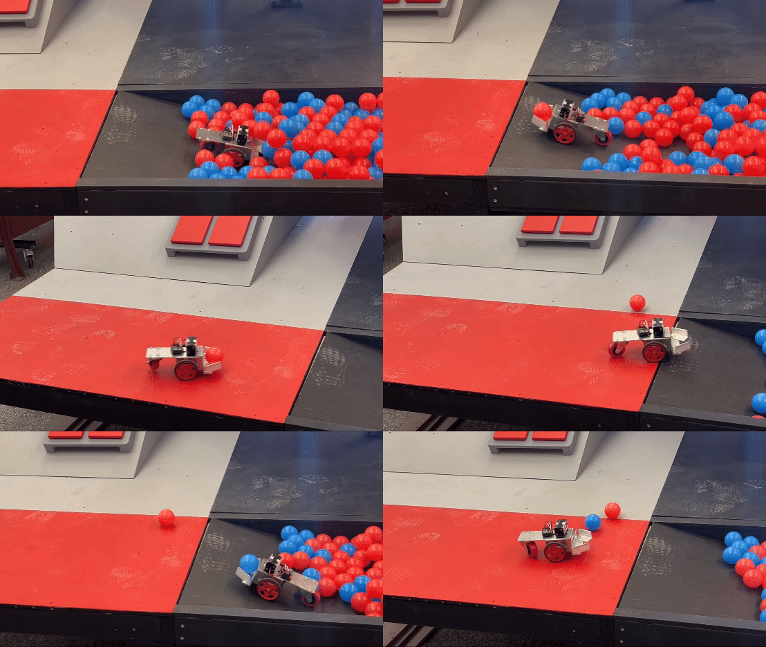
Finally, integrated claw design with MiniMe, holding a ball!
MiniMe effortlessly transporting balls out of the vat of acid — success!
Reaching new heights
With the addition of the front claw, the MiniMe encountered issues climbing the 25-degree incline, which was necessary for later challenges.
I evaluated how battery placement affects the center of mass and how the coefficient of friction and normal force impact wheel traction to ensure no-slip conditions while climbing the ramp.
2. Free Body Diagram and associated equations for all (x, y) positions of the CM to avoid tipping, shown in purple region.
4. Determined CM's y-position using calculated lower x-bound and upper y-bound, and measured x-coordinate.
6. Due to the new CM location directly behind the front axle, the MiniMe successfully climbed the ramp without tipping or slipping!
… now for the fun part!
Problem Statement
Problem Statement
Design a robot to interact with the Gooble Box, a 2x2 button panel on a 25° incline.
The robot must…
start from a colored zone above or below the ramp,
press buttons in an alternating sequence (right-left-right-left),
apply 20N to the top buttons and 10N to the bottom,buttons,
delay for at least 500ms between presses,
stay within a 12x12x16” bounding box, and
maximize points in 90 seconds (1 point / top button, 0.5 point / bottom button).
Design a robot to interact with the Gooble Box, a 2x2 button panel on a 25° incline.
The robot must…
start from a colored zone above or below the ramp,
press buttons in an alternating sequence (right-left-right-left),
apply 20N to the top buttons and 10N to the bottom buttons,
delay for at least 500ms between presses,
stay within a 12x12x16” bounding box, and
maximize points in 90 seconds (1 point / top button, 0.5 point / bottom button).
concept generation:
how many ways can a robot press the buttons?
Decision Matrix
I used a variety of design requirements to motivate the selection rationale and sketched preliminary designs for the top two options.
(2) Inner-Rod Hammers
(5) “Drive-Over-It” Strategy
Most Critical Module (MCM)
To push the buttons, I developed a camshaft design that converts the rotational motion of a motor into the linear motion of shafts. The rotationally offset cams ensure the buttons are pressed at a constant frequency.
Most Critical Module (MCM)
MCM Design Overview
I designed the MCM to be manufactured from simple sheet metal bends, rods, springs, e-clips, washers, and bushings, paying attention to stiffness and reducing misalignment.
Manufacturing and Assembly
Misalignment
Manual machining methods are good for mock-ups, but prototypes require a more precise process.
Learning from the past
I analyzed past successful mechanisms to identify key features to include and avoid when designing my MCM.
The motor shaft is constrained to have one degree of freedom: rotation in y.
The pin shaft is constrained to have one relevant degree of freedom: translation in z.
As the cam turns in +y, it moves the shaft spring in -z by 0.25”, applying force to push the button!
Plasma Cutting
Using this process to cut sheet metal guaranteed much better tolerances than I could produce by hand. This helps to reduce misalignment in shafts and bolted connections, which improves the efficiency of the system.
Bottom with Springs
Assembly was very simple, only requiring steps to bend sheet metal, build the spring subassembly, and bolt the sheet metal structures together.
Final MCM Assembly
Chassis and Drivetrain
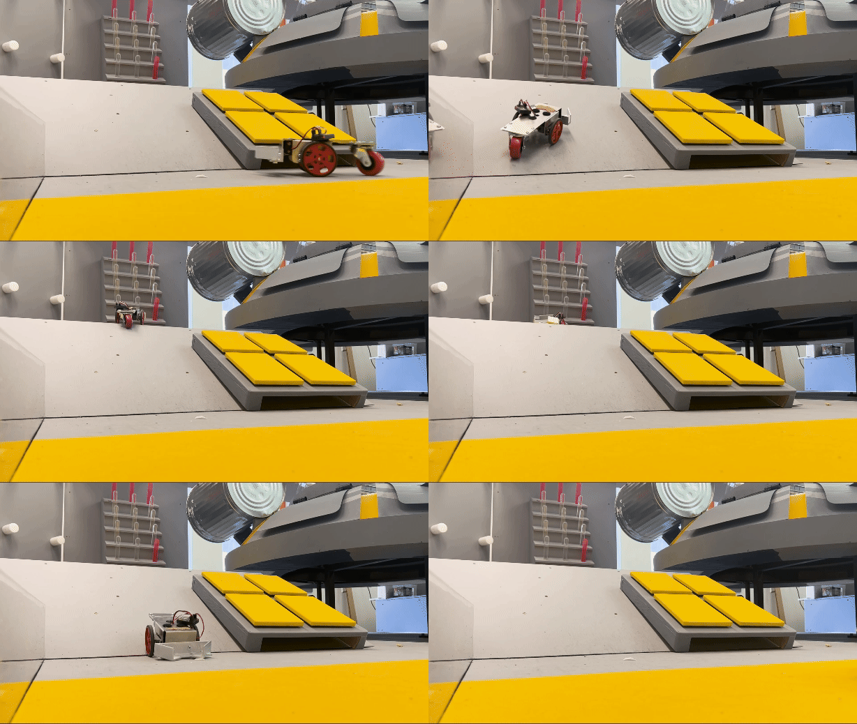
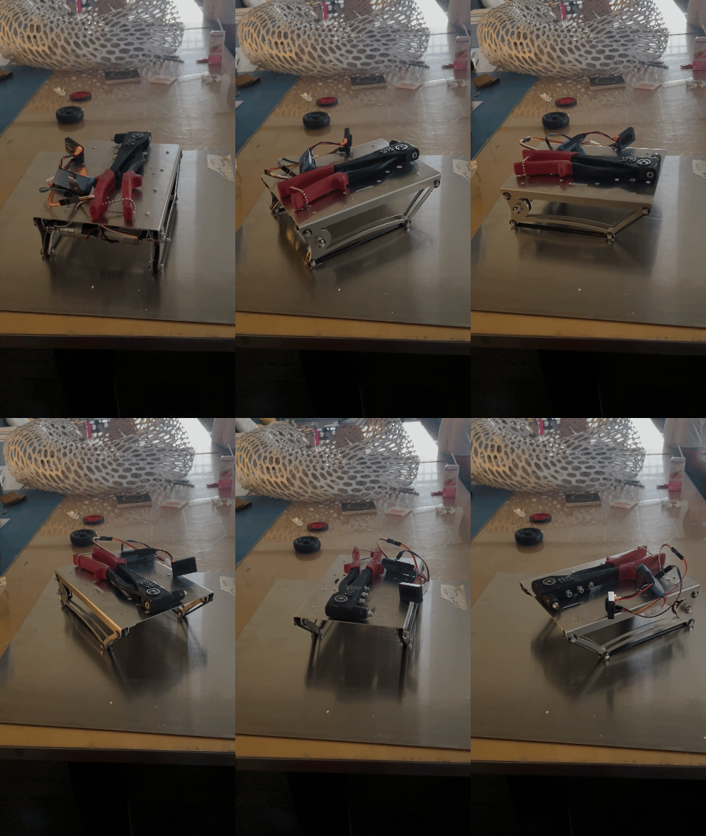
Key Idea: By making a narrow wheelbase, the robot can drive in the space between the buttons. Furthermore, to avoid bottoming out when climbing onto the panel, continuous contact with the ground is maintained with tank treads.
Estimating efficiency and Sizing Motor
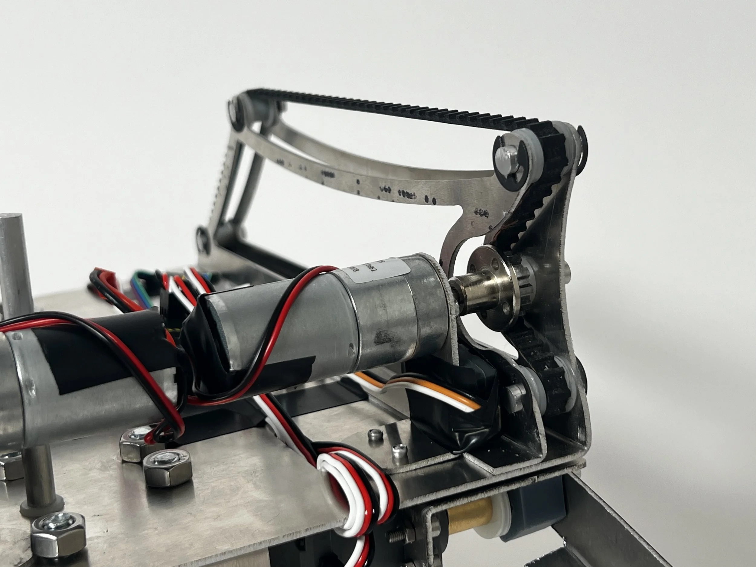
LDO motor interfaces with timing gear, which tensions and drives the belt and moves the robot forwards at a constant speed.
Designing Effective Treads
This design uses a 24-inch timing belt as the tank treads, alongside rods, LDO motors, bushings, e-clips, washers, and custom acrylic timing gears.
Special consideration was given to the minimum number of teeth in contact with the gear to ensure adequate belt tooth shear strength, according to the belt’s datasheet.
I evaluated the effect of bushings, timing gear, and gearbox on the motor's power output. I used this efficiency rating to calculate the maximum torque, assuming a liberal final weight of nine pounds. Based on these calculations, I selected the LDO 98 motor because the expected torque was the closest to peak power output from the provided gearbox configurations (see torque-speed graphs on right).
DESIGN
All chassis components were made with the plasma cutter, employing the same design philosophy as the MCM.
Applying ample force to front face of treads to test motor torque and climbing ability.
The robot can hold two MCM modules, one per row of buttons, while sitting in the empty tracks beside them.
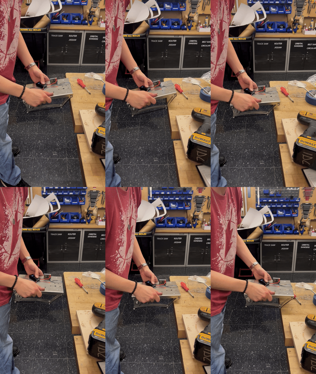
A bending machine and stopper were used to consistently bend sheet metal to 90-degree angles for optimal alignment.
Remote controlling robot to climb on a surface with sharp edges and to ensure the belt teeth appropriately grip the edge and verify the robot does not tip or slip.
Shows the robot in the initial and final stages before and after climbing onto the button panel, emphasizing continuous contact.
Manufacturing
Shows the hole pattern and all parts of the aluminum chassis riveted together before adding the treads and MCMs.
Testing
around the world, around the world, around the world, around the world, around the world
THe Finishing touches
I designed a simple large hook to guarantee the robot was correctly positioned over the buttons every game. This mechanism, affectionately called the stinger, gripped onto the back of the button panel as an alignment feature.
Watch Scorpion In action
Gooble Box Demonstration
Note: Yellow plastic pieces are threaded features to
fine-tune each shaft’s height
Post-Competition Interview
Watch me explain how the robot operates at a live demo during the 2024 2.007 Competition!
acknowledgements
-
I want to give a huge shout-out to my advisor, Professor Warren Seering. Your support was invaluable throughout the semester, and you have made a tremendous difference in my life and my confidence as a mechanical engineer. Thank you for inspiring me every step of the way and always being there to talk to. You are amazing.
-
Thank you to all of the wonderful machine shop staff who worked all hours of the day, especially towards competition season. I want to personally thank Scott for his amazing tips and horrible puns that carried me throughout the semester.
-
In retrospect, I now understand how long assembly and manufacturing take, so my ambitious plans for developing a new MCM every week seem impractical. Perfection is the enemy of progress; I should have experimented more frequently by designing and manufacturing many physical prototypes. I discarded many ideas early on due to a poor understanding and preconceived notions about how components functioned. I have learned to be more experimental and more realistic when planning tasks. I could also have developed a better strategy to gain more points, possibly by experimenting with other modules rather than doing a depth-first search of the gooble boxes.
-
Check it out here!


